Booleans frequently asked questions
Summary: An attempt to unlock the mysteries of Boolean Operations. How and why they work, why they fail, how to fix problems and make them work more consistently, understanding how they work on open objects.
Introduction
Boolean operations can be great time saving procedures for constructing objects in Rhino. But, for the beginner, they seem to often mysteriously fail, and it is difficult to understand why. Hopefully this FAQ explanation will help clarify things a bit. If you don't want to wade through all the following info, you can also try John Brock's short How I fix Boolean Problems
To understand why Booleans fail, first you must understand how they work. They are not some sort of magic tool for putting objects together. They are simply semi-automatic operations that combine several “manual” commands into one process. The Boolean operations basically do 4 things: Intersect two or more objects, Split them at the intersection(s) found, Delete (discard) the parts not wanted, and Join everything back together. Everything you can do with Boolean operations you can also do by “manually” successively using the above four commands. Using a Boolean operation only speeds things up by making it one procedure – when it works…
So, the first thing to keep in mind here is that a solid understanding of how the “component” operations of Booleans work is necessary. When all else fails, you can get the job done with these commands – Intersect, Split, Join and Delete. Try undoing a successful Boolean operation and re-doing it manually using those commands. Get comfortable with the fact that this procedure will always get you where you want to go even if your Boolean attempts fail.
Boolean operation failed...
OK, why do Booleans fail? First and foremost, it is the intersection operation that will determine the success or failure of a Boolean operation. If a correct intersection can be found, the rest is easy. However if Rhino has problems finding the intersection, the Boolean operation is guaranteed to fail. So the whole key is to help Rhino find a good and complete intersection. You can do this by setting up your model and file correctly, and also by understanding some of Rhino’s quirks and limitations.
Intersecting 2 closed (“solid”) objects should produce at least one completely closed intersection curve (i.e. a loop). It’s possible there may be more than one loop if the object intersect in multiple spots – no problem if they’re all closed. If even one is open, however, the Boolean operation will fail. This is because the intersection curve does not completely cut through the objects, and Rhino doesn’t know how to finish the cut, so it stops and gives you an error message.
Note: Doing Boolean operations on open objects is also possible, but a bit more complicated, so we’ll assume at first that all objects are closed. Open objects will be covered later.
So, having taken the above into account, if your Boolean operation fails, the first thing you should do is check the intersection of the objects. Select your objects and call Intersect. First, look at the intersection curve(s)on the screen. Does it look correct? Are there any visible gaps or extra segments or other things that “look strange”? If so, you need to find out why. If the intersection looks OK, but the Boolean is still failing, while the intersection curve is still selected, go into Properties > Details or just use the command What. The resulting info box should tell you all you need to know about the curve. Does it say the curve is open? That will be your problem area then. More than one curve? You need to find out why there are either gaps or overlaps in your intersection.
Intersection problems, solutions and limitations
What can cause gaps or problems in your intersection? There are many possibilities. Some are due to modeling errors or inaccuracies, some are due to Rhino’s limitations. Let’s look at the common errors first:
If you think your intersection should be closed, but it’s not, select the curve, and call CrvStart, which will place a point at the start of the curve. Normally this will correspond with one side of the gap. Zoom in closely and see if you can see the gap on the screen. Why is there a gap there? Well, maybe you think that your objects are closed, but they’re really not. The intersection may cross a gap between surfaces, and that will cause an open curve. If you have forced together your object using JoinEdge, that may also happen, even though the object says closed. The other thing to check is your modeling tolerances (see Tolerances FAQ), if they are too large, this may prevent the intersector function from finding a complete intersection, even though all else is well. Try tightening your tolerances and running the Boolean again. Once you get a full closed intersection, your operation should work…
If you can’t get Rhino to automatically produce a closed intersection curve even after you have fixed your object the best you can, it may be time to go back to “manual”. Get the best intersection curve you can and try editing it until you have a closed object. You may need to add or modify a segment, do some point editing, take out overlapping segments, or something like that. Once you have this curve, you can try trimming your objects individually. You will need to explode your polysurfaces to trim with the intersection curve. Trim out the parts you don’t want and join all back up.
Known Rhino limitations:
Coincident seams – all objects have seams, sometimes when the seams on two objects are at exactly the same place, Rhino will have trouble with the intersection. Solution – either try to move the seam, or try moving one object just a tiny, tiny bit (if you can without making your model inaccurate). Or try to do the operation “manually”.
Coplanar faces – if two faces of an object are on the same plane, Rhino may not be able to calculate the intersection. This is a fairly common occurrence, try to avoid building your model this way if you can. Solution – as above, you may move the object slightly if possible, if not, you may have to do this operation “manually”.
Nearly tangent surfaces – like the intersection of two equal diameter pipes at an angle. The intersection often fails at the point where the surfaces are tangent. There is no easy fix currently for this problem.
Invalid objects – If one of the objects you're trying to work with is invalid, Boolean operations will often fail. Check for invalid objects by using the command SelBadObjects. If one highlights, you will need to fix it first before proceeding. It is also recommended that you turn on automatic object checking, if invalid objects are created in the course of your work (or imported), Rhino will tell you immediately. To do this, simply type CheckNewObjects. This is a toggle, running the command again turns it off.
Non-Manifold Polysurfaces – Although Rhino doesn't currently flag these objects as bad, they can cause failure. Rhino shouldn't create these types of structures, but under certain conditions it does, especially with V4. The only way to find them currently is to check the properties of the object.
"Manual" construction and editing is sometimes needed
Animated illustrations showing manual surface construction and editing when Boolean operations fail.
How to Manually Edit Surfaces with Coplanar Faces and Nearly Tagent Surfaces
How to Manually Edit Surfaces with Coplanar Faces II
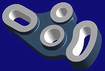
This is an example of a solid that can not be constructed with solid primitives and surface editing techniques are required.
- The main problem is the condition of the side surfaces that are coincidental and do not shared a volume with the main solid piece. When Booleans fail, rely on using surface editing techniques as described in the steps in the linked document.
- Download the model
Boolean operations on open objects
As mentioned above, Boolean operations can also be performed on open objects. The principle is the same, but since the objects are not closed, we have a couple of extra things to do and understand. Rhino V4 provides a tool that makes the following procedure much easier if you have only two objects, see the command: Boolean2Objects
Surface Direction
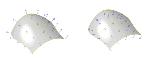
First, it is necessary to understand the concept of surface normals and direction. Every surface object has a “sided-ness”, that is to say a “front side” and a “backside”. This is called the “direction” in Rhino and can be shown with the Dir command. Try using Dir on several different surfaces and see what happens. The direction arrows point to the “outside” of the surface, and they also show the local “normal” direction, that is to say they are at 90º to the surface locally.
For each surface, you can flip the direction of the normals (i.e. invert the sided-ness of the surface. To do this, while you're in the Dir command, you either type “F” and enter, or just click once on the surface. You will see the direction arrows flip sides. You can also do this outside the Dir command by using the command Flip (you will not see any arrows, though).
Note: Curves in Rhino also have a direction which can be shown by the Dir command. In this case, Flip exchanges the start and end points and reverses the curve direction.
When surfaces are joined, Rhino tries to “uniformize” the surface normals of the object, that is to say, it tries to keep all adjacent surfaces having the same front/back orientation. Thus when you have an open set of joined surfaces (an open polysurface), it will still have one uniform front/back and not be a patchwork quilt of surfaces facing in different directions.
Experiment: Make a square. Extrude it into a 4 sided open box. Explode it into separate surfaces. Using Dir, flip two of the surfaces' directions to the inside. Now window select them all and use Join to make them into a 4 sided polysurface again and use Dir again to see what happened to the surface directions.
When an object is closed in Rhino, the program automatically flips all the surfaces to the outside. It assumes we don't care about the inside anymore, because the object is closed (solid). Closed polysurfaces cannot have their normals facing inside (try to see if you can with Dir). If you do manage to flip the normals of a closed polysurface to the inside, either - it isn't really closed, or, you have discovered a (very rare) bug.
Experiment2: Make a cube. Explode it into separate surfaces. Using Dir, flip a few of the surfaces' directions to the inside. Now window select them all and use Join to make them into a polysurface again, and see what happens to the surface directions.
How surface direction affects Boolean Operations
OK, now you understand about surface normals and direction. Why is this important in Boolean operations, anyway? When Rhino is instructed to perform a Boolean operation, it looks at the surface normals to determine which parts to keep and which parts to throw away. Essentially, Boolean Union, Difference and Intersection are all the same operation, just different parts of the objects are kept at the end. With Boolean Union, for example, the parts that overlap are thrown away and the rest joined together. With Intersect, it is exactly the opposite.
Booleans with “solids” (closed polysurfaces) are predictable, because all surface normals always point to the outside. With open polysurfaces, however, the results can seem unpredictable, as we don't immediately know which is the front or back of each object without using the command Dir.
Note: If you are doing Boolean operations on closed polysurfaces and they don't react the way you think they should (i.e. the wrong parts disappear), probably one or more of your objects aren't really closed and have the normals pointing inward. Use Dir to see.
Tip: One way to always be able to know which way surfaces are facing is to set up your display to show backfaces in a different color from front faces. In V3, use the command AdvancedDisplay > Color Backfaces to set this up. In V4, it's Options>Appearance>Advanced Settings>Shaded>Backface Settings, set “single color for all backfaces”, and choose a color. Note, this only works if you are working in Shaded Viewport mode, in Wireframe, Ghosted or Rendered you will not see this.
Let's imagine the simplest “open” Boolean operation. You have one “solid” closed polysurface that is fully intersected by a single surface. You can easily create this by making any kind of solid object, then using the CutPlane command and drawing a cut line through your object in any direction you desire.
Now, try BooleanDifference (BD). Select the solid as the first set and the cut plane as the second. One side or the other of the solid will be “cut off” and the hole filled by the plane. But which side???
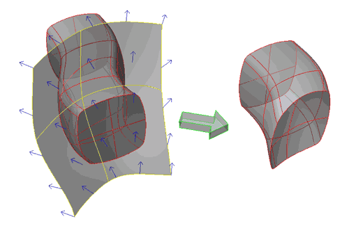
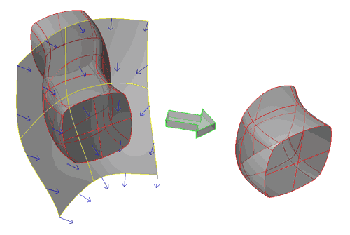
You can't know unless you call Dir on the surface. Look at the direction of the surface normal. Then do your difference. Undo, flip the direction of the surface using Dir , then try the difference again. The direction of the surface normal of the plane will determine which piece gets left.
In general, if you want to BD between an open (poly)surface and a solid to work as if it was two solids, the surface normals of the open object should point towards the solid object - just as if it were also a solid.
In V4, Boolean2Objects allows you to cycle through all the possibilities of the different Boolean operations and see the result on-screen, you can then chose the result you want. This only works currently with just two objects.


