Advanced Rhino Display Modes
Summary: Rhino 5 added a new display mode with hidden lines, sketch modes, and other options. You can download and use them with your current Rhino, too.
Contents
Background
A little explanation is in order….
Rhino 5 added many more advanced display options that can be configured to create more advanced, realtime display modes. These additional display options include shadows, edge thickness by type, and lighting control. For a basic understanding of advanced display in Rhino, go to:
- A video by Rhino Visual Tips 5.0: Chapter 9: Rhino Options: Display Modes
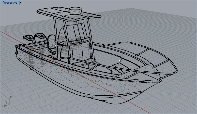
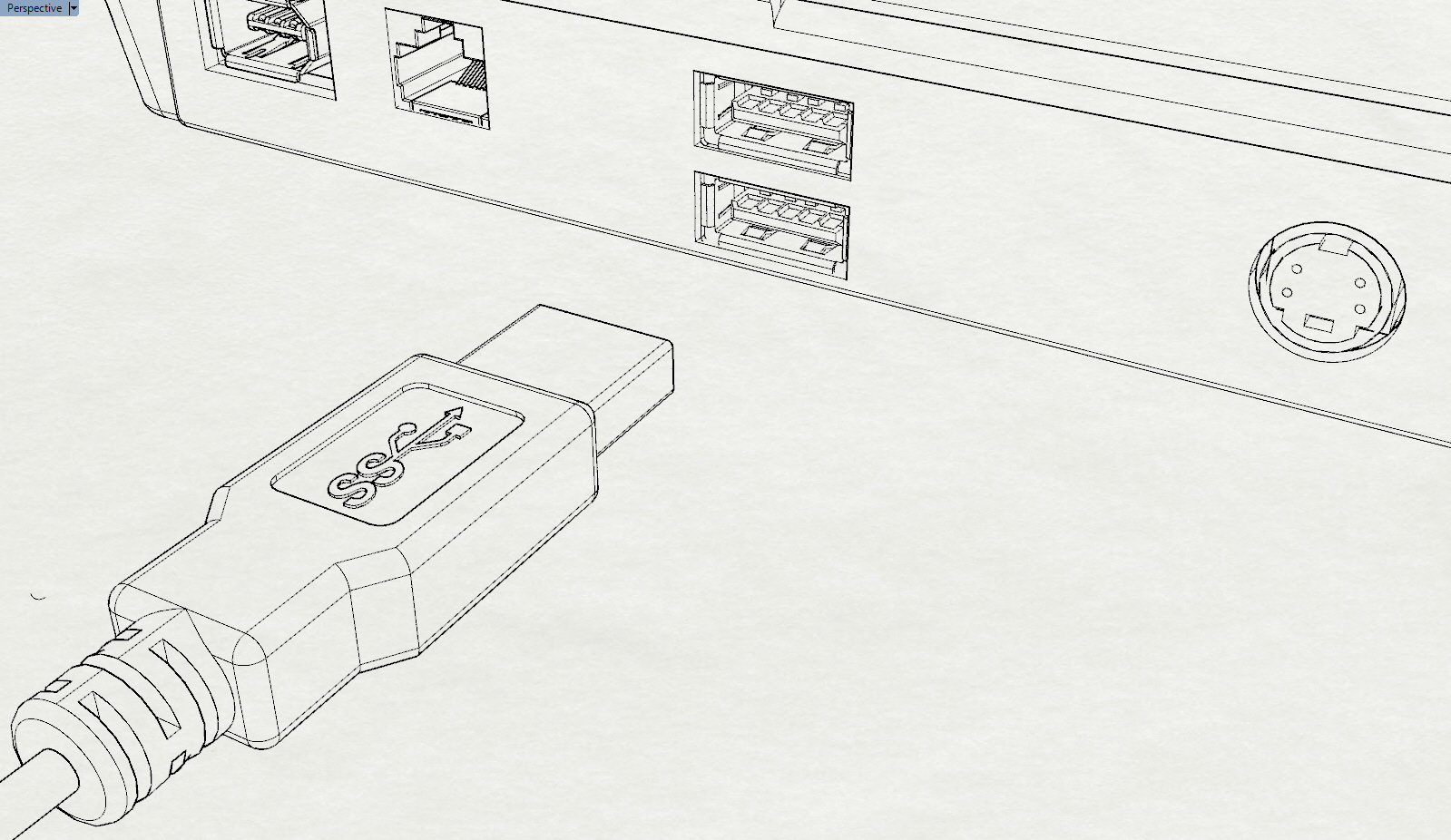
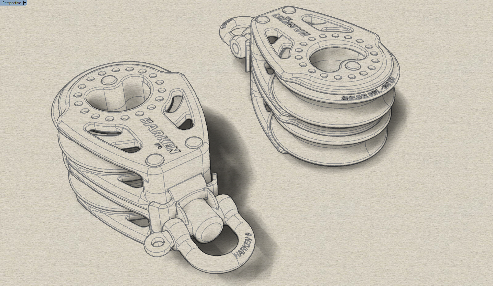
Here are examples of the new default display modes. There are three new modes available:
Technical
Pen
Artistic
space space space
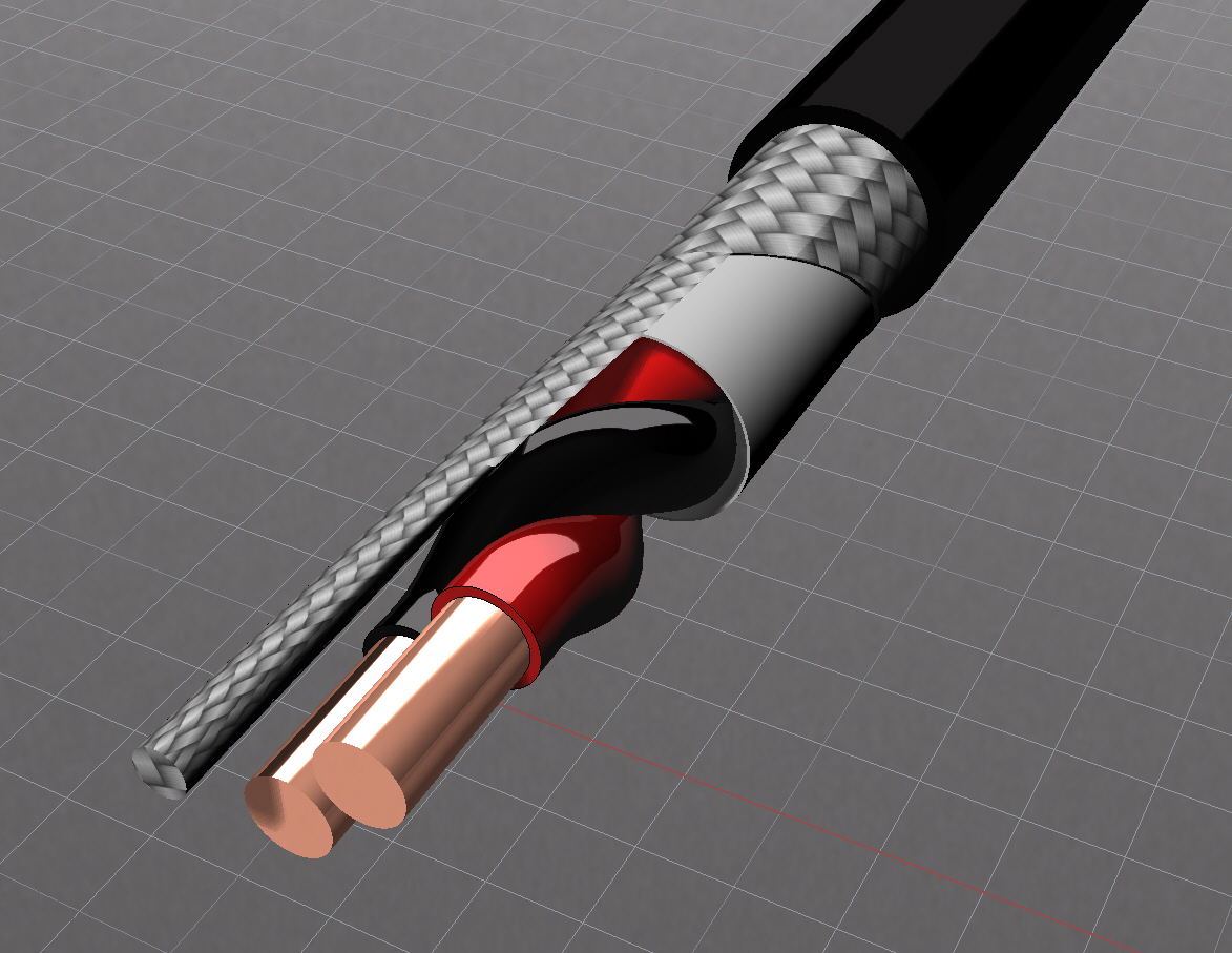
The rendered display mode has been upgraded. By adding a few materials and turning on an environment, this is possible. A video tutorial is available here: Materials, Environments and more!
Rendered
Additional custom examples
To use the full power of these new display options, you can create your own display modes and control:
- Unordered List ItemReal-time silhouettes
- Creases
- Borders
- Real-time intersections
- Blended Shaded and Rendered Display
- Shadow types
Installation
The modes below can be imported into Rhino through the Rhino Display Options import command. Go to the Tools menu > Options >View > Display Modes page and click Import. Navigate to the downloaded .ini files and import. See the Advanced Display help topic under the import heading.
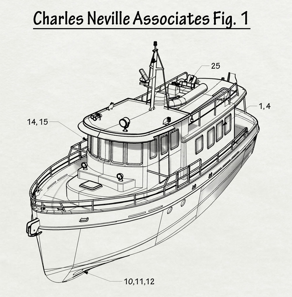
Patent
Download the Patent.ini file to add this mode.
This mode is quite sensitive to shadow settings. Some of the options to experiment with in this mode. Shadow line angle? Try 0, 23, 45, 90 degrees. 23 has some interesting characteristics. The shadow line does not stair-step at 23 degrees. Adjusting the lines widths option under Patent > Objects > Lines is quite important.
By using the Layout mode you can set up the title block and leader text.
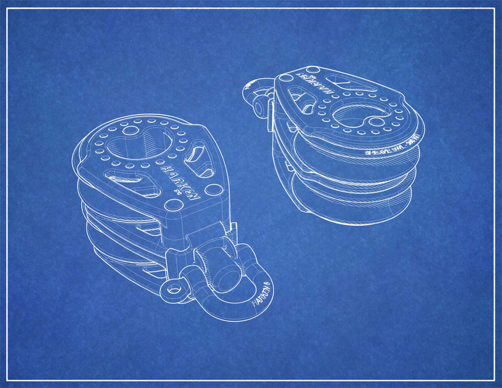
Blueprint
Blueprint is a combination of a bitmap background, white striped shadows and thick silhouette lines. To use this mode, download the Blueprint.ini and the Blueprint background bitmap. Set the display mode to use this image as the background. This mode also can work with the http://crisazi.deviantart.com/art/Blackboard-150161848|blackboard background]].
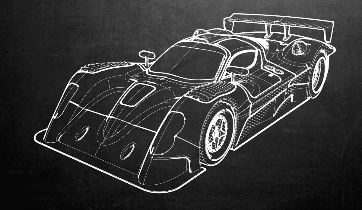
Blackboard
This mode is similar to the blueprint mode. It uses an image in the background and white shadows, but uses much larger over-sized widths to simulate more of a sketch mode. Download Blackboard.ini file for the settings and the chalkboard bitmap.
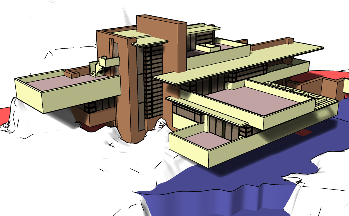
Simple Bright
A simple bright colored shaded mode popular in both architecture and mechanical design. To run this mode import the Simple Bright.ini file.
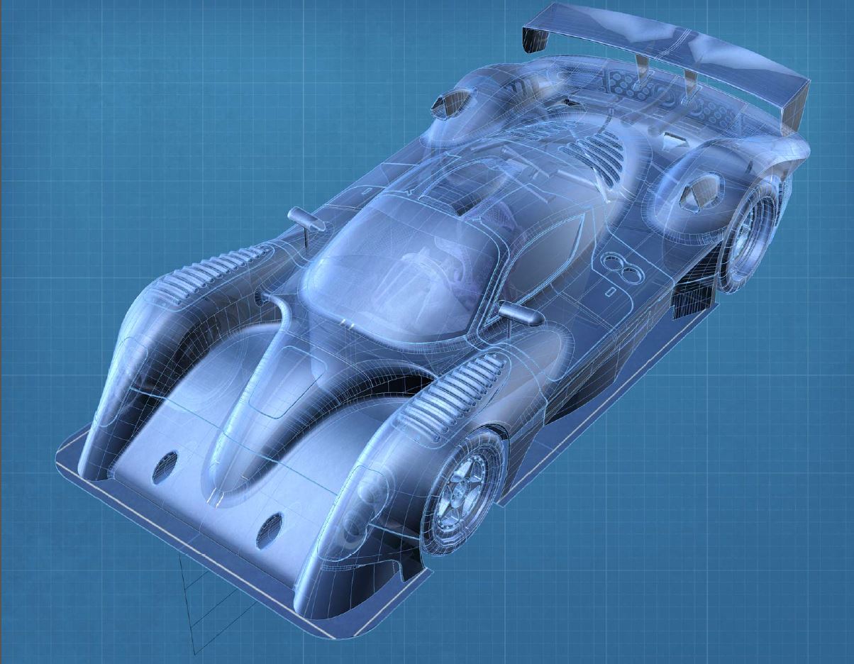
Ghosted Blueprinting
This mode is similar to the blueprint mode although the objects are partially transparent and surfaces lightly shaded and modeled. To run this mode, import Ghosted Blueprint.ini. There is also a bitmap background to download: Blueprint Grid
Printing Advanced Modes
The advanced display modes are currently based on display screen resolutions (edges 2 pixels wide for example). When printing these modes, the resolution of the print to the printer can be very different from display. It is possible that a 4-pixel thick line will look thick on the display, but when printed the edges do not look thick. This change may apply to shadows and hatching. To complicate the issue even more, the print preview does not preview these effects correctly. This is something that needs to be improved. Below is a workaround to this problem.
If you would like to print one of these modes, create a copy of the on-screen mode and create a print version of the mode. For instance the Patent mode uses edges of 4 for screen display. In the Printer version of the display mode the edges are 8 pixels. Below is a table which compares a screen version of the mode vs a printable version of the mode:
| Patent Mode | Patent Print mode | |
|---|---|---|
| Shading Mode | Parallel Lines | Parallel Lines |
| Shaded mode lines | 1 px | 4 px |
| Shaded mode separation | 3 lines | 2 lines |
| Edge Line Thickness | 1 px | 2 px |
| Silhouette Thickness | 2 px | 8 px |
Limitations
- You cannot assign any of these display modes to individual objects (i.e. SetObjectDisplayMode). However, once in a Technical display mode, you can assign all other modes to individual objects…in other words, Technical mode is a superset of all other modes (that support the standard OpenGL pipeline). Thus, you can still mix and match object display modes, you just have to start in the Technical mode.
- Initial calculations of the technical display data can take a long time for dense mesh objects…and there's nothing we can do about that…and if the object changes in any way, the calculations have to be redone.
