Sidebar
PanelingTools Commands
Summary: Command descriptions of PanelingTools plug-in for Rhino 4.0
Background
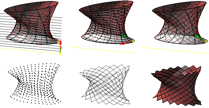
Panels are repeated patterns on surfaces, polysurfaces, or a grid of points. PanelingTools offers two ways to create panels. The first is to use an ordered paneling grid of points (ordered by row and column) and the second is by objects (NURBS surface or polysurface). Panels are added in the form of edges, faces borders, face patches, flat faces, and a mesh. All panels are serialized.
PanelingTools use some geometry concepts such as NURBS curves and surfaces, the U and V direction of a NURBS surface, trimmed vs untrimmed surfaces and polysurfaces. For a quick review, you can check the NURBS Surfaces wiki page.
Paneling by ordered grid of points
- Step one: Create an ordered grid of points
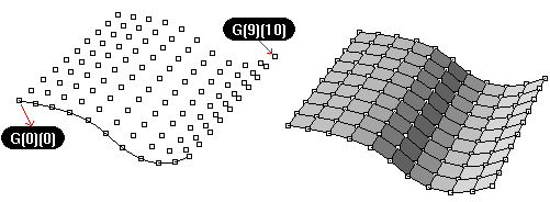
Points must be ordered in rows and columns. Each point location is marked in its object name (shows in the object properties).
Syntax is: Name(intRow)(intColumn)
While PanelingTools offers many commands to create the ordered grid, you can create your own, through scripting for example. All that is required is to name point-objects and use for paneling.
Another advantage of separating grid generation from paneling is that you can edit the grid before paneling. You can run commands like pull, project, or transform to edit the grid, then panel.
- Step two: Create panels
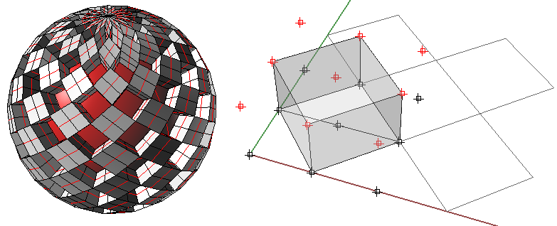
Select an ordered point grid, a reference object (optional), pattern, and the kind of output you like to get. Custom paneling and quads is also possible.
Paneling surfaces and polysurfaces directly
These are tools to panel directly using a reference surface or polysurface.
It is also possible to combine grid generation commands with paneling by grid commands using macros. Here is an example where you can have a PanelByGridArray:
ptGridArray Pause Pause ptPanelGrid _Enter
Command descriptions
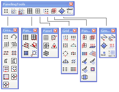
Toolbars
PanelingTools toolbars offers two sets of scripted commands that combine grid generation with paneling. Toolbars are available to download.
Menu
Note that the PanelingTools drop-down menu shows only after PanelingTools is loaded (usually after calling one of the plug-in commands for the first time in a session).
Available commands
ptDivideCurveSpan
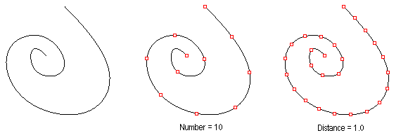
Find curve division points by number or distance on curve.
Command options:
 Method (Number, ArcLength)
 Method=Number:
   NumberOfSpans: Number of spans on curve.
 Method=ByDistance
   Length: on curve, between divide curves.
   Round: Option to round distances to fill the span of the curve
   RoundingMethod: Up or down
 Group: Option to group result
ptDivideCurveByDirectDistance
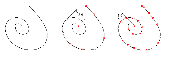
Find curve divide points by direct distance
Command options:
 Distance: Direct distance between points
 AddEndPoint: Add end point
 Group: Option to group result
ptPanelSurface
Using a base surface, the command generates the paneling grid and panels.
Command options:
 DivideMethod (BySurfaceUV, BySurfaceDistance)
 DivideMethod=BySurfaceUV:
   U_Method (Number, ArcLength) – First surface direction divide method.
     U_NumberofSpans: Number of spans.
     U_Length: Distance on base (first) iso-curve.
     U_Round: Option to round distances to fill the span of the curve
     U_RoundingMethod: Up or down
   V_Method (Number, ArcLength) – Second surface direction divide method.
     V_NumberofSpans: Number of spans.
     V_Length: Distance on base (second) iso-curve.
     V_Round: Option to round distances to fill the span of the curve
     V_RoundingMethod: Up or down
 DivideMethod=BySurfaceDistance
   U_Length: Distance in first direction
   V_Length: Distance in second direction
   Extend: Option to extend surface when calculating the grid (get better converge)
 Pattern (Box  BoxX  Triangular  TriBasic Dense  Diamond  AngleBox  Wave  Brick New)
 PanelShape (Straight, Pull)
 AddPointsGrid: Add grid of points
 AddEdges: Add paneling edges
 AddFacesBorder: Add face outlines
 AddFaces: Add face patches (this can be time consuming for large sets of panels)
 AddFlatFaces: Calculate and trim best fit planar panels.
   BestFit - Best fit through all four panel points (0,1,2,3)
   TangentToCenter (only when there is a bse surface) - plane tangent to surface at the center of panel
 AddMesh: Add a mesh
 Group: Option to group result
 Name: Name of panels
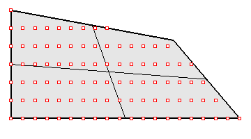
ptPanelCurve
Generate panels for a surface or polysurface using direction curve. Curve can be open or closed.
 Line: Option to define direction curve with two points
 CurveOptions
   NumberOfCuts: Number of curves to be projected to object
   Spacing: Distance between curves
   ExtrudeDirection: Extrusion direction
   ProjectionDirection: Projection direction
 GridOptions
 Method (Number, ArcLength) – curve divide method.
   NumberofSpans: Number of spans.
   Length: Distance on base (first) iso-curve.
   Round: Option to round distances to fill the span of the curve
   RoundingMethod: Up or down
 Pattern (Box  BoxX  Triangular  TriBasic Dense  Diamond  AngleBox  Wave  Brick New)
 PanelShape (Straight, Pull)
 AddPointsGrid: Add grid of points
 AddEdges: Add paneling edges
 AddFacesBorder: Add face outlines
 AddPatchFaces: Add face patches (this can be time consuming for large sets of panels)
 AddFlatFaces: Calculate and trim best fit planar panels.
   BestFit - Best fit through all four panel points (0,1,2,3)
   TangentToCenter (only when there is a bse surface) - plane tangent to surface at the center of panel
 AddMesh: Add a mesh
 Group: Option to group result
 Name: Name of panels
ptManage3dPatterns
Create new 3D patterns that connect grid points, save, delete, or edit them. These patterns are saved to document and are listed in commands like ptPanel3D with other built-in patterns.
Command options:
 New: For creating new pattern
 Edit: To edit existing patterns
 Delete: To delete existing patterns
ptPanel3D
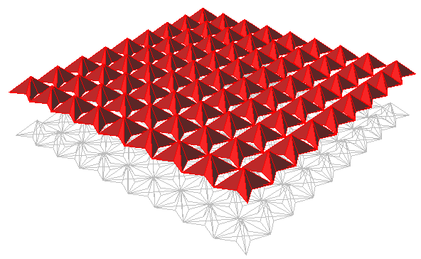
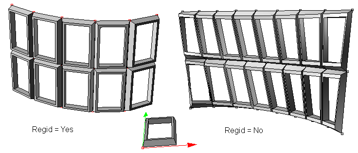
Panel with two grids. There are a few predefined patterns to select from. There is also the option to create a new pattern that connects grid points. Panels are added in the form of edges, faces, and polysurfaces. Spacing of unit patterns depends on grid spacing.
Command options:
Pattern (WireBox Partitions Box Wedge Pyramid1 Pyramid2 New). The **New** option for patterns allows creating a user-defined pattern.
 Group: Option to group result
 Name: Name of panels
ptPanel3DCustom
Morphes 3D patterns between two bounding grids. There is the option to select a base surfaces.
 Base_x: Start x index relative to grid
 Base_y: Start y index relative to grid
 Shift_x: Spacing betweenpattern un itis in x direction
 Shift_y: Spacing betweenpattern un itis in y direction
 X_Length: Scale is x direction
 Y_Length: Scale is y direction
 Z_Length: Scale is z direction
ptOrientToGrid
Allows selecting any number of objects, then orient (flow) them along paneling grid. It is possible to select a base surface. You can select three reference points and the fourth point is an option to deform pattern to fit the grid.
 Base_x: Start x index relative to grid
 Base_y: Start y index relative to grid
 Shift_x: Spacing betweenpattern un itis in x direction
 Shift_y: Spacing betweenpattern un itis in y direction
 X_Length: Number of unit grids to map to in X direction
 Y_Length: Number of unit grids to map to in Y direction
 Flip: to change normal direction.
ptManage2dPatterns
Create new patterns that connect grid points, save, delete, or edit them. These patterns are saved to the document and are listed in commands like ptPanelGrid with other built-in patterns.
Command options:
 New: For creating new pattern
 Edit: To edit existing patterns
 Delete: To delete existing patterns
ptPanelGrid
Panel with ordered grid of points. Reference object (surface or polysurface) is optional. There are a few predefined patterns to select from. There is also the option to create a new pattern that connects the grid points. Panels are added in the form of edges, faces borders, faces (edgesrf or patches), flat faces, and a mesh.
Command options:
 Pattern (Box  BoxX  Triangular  TriBasic Dense  Diamond  AngleBox  Wave  Brick, etc(user defined patterns))
 PanelShape (Straight, Pull)
 AddEdges: Add paneling edges
 AddFacesBorder: Add face outlines
 AddFaces: Add face patches (this can be time consuming for large sets of panels)
 AddFlatFaces: Calculate and trim best fit planar panels.
 FlatFacesMethod
   BestFit - Best fit through all four panel points (0,1,2,3)
   FitBasePt0 - Fit through points 0,1,2
   FitBasePt1 - Fit through points 1,2,3
   FitBasePt2 - Fit through points 2,3,0
   FitBasePt3 - Fit through points 3,0,1
   TangentToCenter (only when there is a bse surface) - plane tangent to surface at the center of panel
 AddMesh: Add a mesh
 Group: Option to group result
 Name: Name of panels
ptPanelGridCustom
Panel grid with user-defined pattern curves and points. There are options to scale pattern relative to the grid.
Command options:
 GridWidth: Width of the grid.  Default to pattern width.
 GridHeight: Height of the grid.  Default to pattern height.
 U_Spacing: Unit spacing in first direction.
 V_Spacing: Unit spacing in second direction.
 Group: Option to group result
 Name: Name of panels
ptPanelGridQuads
Adjust paneling grid to create maximum number of quads within tolerance.
One way to have better quads coverage is by increasing MaxDeviation, but that increases distortion. Another way is to use a more dense grid.
Command options:
 MaxDeviation: Deviation from base grid - higher deviation=better coverage and more distortion
 Triangulate: option to split remaining non-planar faces into triangles
 Group: Option to group result
 Name: Name of panels
ptAnalyzeFlatFaces
Color panels or faces (perviously created with FlatFaces option in paneling commands) from red to blue based on their deviation from base point grid or surface (red=furthest).
ptPanelRandomPoints
Select base surface, any number of points on surface, or have the command generate points.
Command options:
 GenerateRandomly: Random generation of points.
 PointCount: Number of points. Appears only when GenerateRandomly=Yes
 PanelShape: Straight or Pull
ptPanelSubDivide
Select base surface, any number of closed polylines with end points on surface.
Command options:
 Degree: Number of subdividing steps.
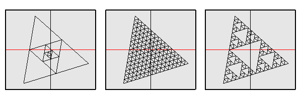
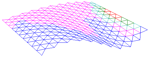
 Method: All/SubsOnly/MainOnly. Different methods of sub-paneling as in the image.
 PanelShape: Straight or Pull
ptTriangulatePoints
Use Delauney triangulation to create a mesh from points.
ptGroupSimilarPanels
Group similar curves together within given tolerance.
ptGridArray
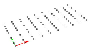
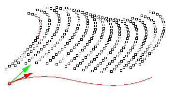
Create an array of ordered points. You define the first and second directions. (These need not be orthogonal.)
Command options:
 U_Number: Number of elements in U (first) direction.
 U_Spacing: Distance between elements in U direction.
 U_Direction: Option to set new U direction.
 V_Number: Number of elements in V (second) direction.
 V_Spacing: Distance between elements in V direction.
 V_Direction: Option to set new V direction.
 Group: Option to group resulting point grid
 NameOfGrid: Grid name
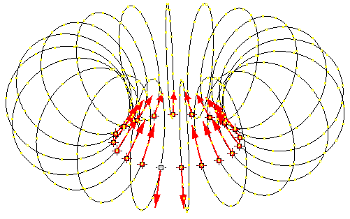
ptGridArrayPolar
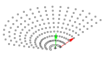
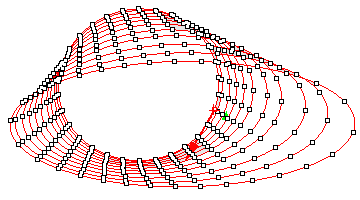
Array need not be flat. You select rotation center and axis, then set base point and direction of the polar array.
Command options:
 U_Number: Number of elements in U (first) direction.
 U_Spacing: Distance between elements in U direction.
 U_Direction: Option to set new U direction.
 V_Number: Number of elements in V (rotating) direction.
 V_Angle: Angle between elements.
 Group: Option to group resulting point grid
 NameOfGrid: Grid name
ptGridExtrude1
Select a direction curve and create a parallel or polar grid.
Command options:
 U_Method (Number, ArcLength or DirectDistance) – Curve divide method.
   U_NumberOfSpans: Number of divide points.
   U_Length: Distance on curve.
   U_Round: Option to round distances to fill the span of the curve
   U_RoundingMethod: Up or down
   U_Distance: Direct distance
   U_AddEndPoint: Option to ad end point on curve
 V_Number:  Number of points in second direction.
 V_Method (Parallel, Polar) – extrusion method
   V_Distance: Distance value.
   V_Direction: Option to define second direction
   V_Angle: Angle value
   V_RotationAxis: Option to define rotation axis
 Group: Option to group resulting point grid
 NameOfGrid: Grid name
ptGridExtrude2
Sort of like extrude along a curve. Select two curves and define the divide method of each curve (by number, by distance, or by direct distance).
Command options:
 U_Method (Number, ArcLength or DirectDistance) – First curve divide method.
   U_NumberOfSpans: Number of divide points.
   U_Length: Distance on curve.
   U_Round: Option to round distances to fill the span of the curve
   U_RoundingMethod: Up or down
   U_Distance: Direct distance
   U_AddEndPoint: Option to ad end point on curve
 V_Method (Number, ArcLength or DirectDistance) – First curve divide method.
   V_NumberOfSpans: Number of divide points.
   V_Length: Distance on curve.
   V_Round: Option to round distances to fill the span of the curve
   V_RoundingMethod: Up or down
   V_Distance: Direct distance
   V_AddEndPoint: Option to ad end point on curve
 Group: Option to group resulting point grid
 NameOfGrid: Grid name
 SwitchCurves: Switch which of the two direction curves is rail and witch is cross section.
ptGridUCurves
Divide parallel curves (or usually non-intersecting). Selection must be in the order of desired rows. The command divides those curves by selected method. It also unifies directions of curves.
Command options:
 Method (Number, ArcLength or DirectDistance) – Curves divide method.
   NumberOfSpans: Number of divide points.
   Length: Distance on curve.
   Round: Option to round distances to fill the span of the curve
   RoundingMethod: Up or down
   Distance: Direct distance
   AddEndPoint: Option to ad end point on curve
 Group: Option to group resulting point grid
 NameOfGrid: Grid name
ptGridUVCurves
This is for those who have all curves in both directions and would like to make a grid out of curves intersections.
Command prompts to select curves in each of the two directions to make the grid. Selection order defines order of rows and columns in the grid.
Command options:
 Group: Option to group resulting point grid
 NameOfGrid: Grid name
ptGridPoints
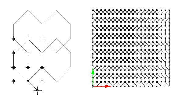
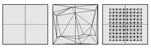
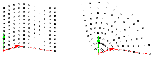
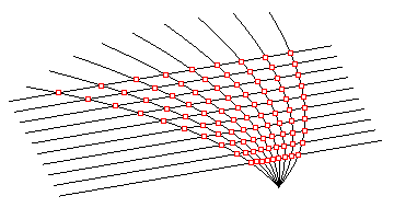
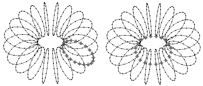
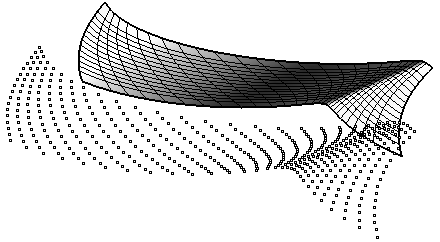
Input grid u and v directions, base point, and u and v spacing. Using input, a base grid is created. Input points are rounded to the closest grid intersection points. This is why the result might be fewer points then the input. (Multiple points can be rounded to same index.) For a random set of points, the higher the spacing the more successful it will be to panel these points as illustrated in the image below.
If align option is set to Yes, points will shift location slightly to align with the defined spacing.
 U_Spacing: Reference grid spacing in the first direction.
 U_Direction: Option to set first direction
 V_Spacing: Reference grid spacing in the second direction
 V_Direction: Option to set second direction
 Group: Option to group resulting point grid
 DeleteInput: Delete input points
 AlignPoints: Align resulting points grid with reference grid
 NameOfGrid: Grid name
ptGridPointsOnSurface
Use this command to order existing points on a surface by that surface's UV.
Algorithm: Using input tolerance, surface is scanned for points (with u-dir iso-curves with spacing = 2*tolerance). If at least one point is found on the scan curve, then a row is created and added to grid. If align option is set to Yes, points will shift location to align with scan line.
 Tolerance  : Round points by this tolerance (reference spacing = 2* tolerane)
 Group: Option to group resulting point grid
 DeleteInput: Delete input points
 AlignPoints: Align resulting points grid with reference grid
 NameOfGrid: Grid name
ptGridSurfaceUV
Divides a surface following its U and V directions. Division can be by number, distance, or a combination. Note that grid name follows surface name.
Command options: DivideMethod (BySurfaceUV, BySurfaceDistance)
 U_Method (Number, ArcLength) – First surface direction divide method.
   U_NumberofSpans: Number of spans.
   U_Length: Distance on base (first) iso-curve.
   U_Round: Option to round distances to fill the span of the curve
   U_RoundingMethod: Up or down
 V_Method (Number, ArcLength) – Second surface direction divide method.
   V_NumberofSpans: Number of spans.
   V_Length: Distance on base (second) iso-curve.
   V_Round: Option to round distances to fill the span of the curve
   V_RoundingMethod: Up or down
 Group: Option to group resulting point grid
ptGridSurfaceDistance
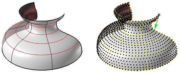
Select a surface, divide by direct (spatial) distances. This command uses an algorithm where points are calculated incrementally (every new point depends on previously created points). This is why it might not give complete coverage. Note that grid name follows surface name. The command lets you select a point on surface to use as base.
Command options:
 U_Distance: Distance in first direction
 V_Distance: Distance in second direction
 Extend: Option to extend surface when calculating the grid (get better converge)
 Group: Option to group resulting point grid
ptGridCurve
Generate a grid based on an object and direction curve. Curve can be open or closed.
Command options:
 Line: Option to define direction curve with two points
 CurveOptions
   NumberOfCuts: Number of curves to be projected to object
   Spacing/Angle: Distance between curves
   ExtrudeMethod=Parallel/Polar
   ExtrudeDirection: Extrusion direction (for parallel)
   ProjectionDirection: Projection direction
 GridOptions
 Method (Number, ArcLength) – curve divide method.
   NumberofSpans: Number of spans.
   Length: Distance on base (first) iso-curve.
   Round: Option to round distances to fill the span of the curve
   RoundingMethod: Up or down
 Group: Option to group resulting point grid
 NameOfGrid: Grid name
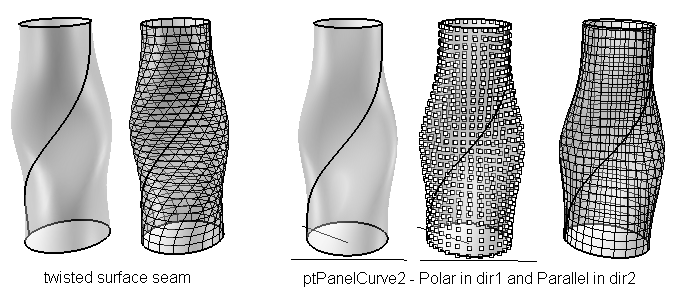
ptGridCurve2
Generate a grid based on an object and two direction curves. Curves can be repeated in parallel or polar direction.
 Line: Option to define direction curve with two points
 FirstDirCurvesOptions (same for SecondDirCurveOptions)
   NumberOfCuts: Number of curves to be projected to object
   Spacing/Angle: Distance between curves
   ExtrudeMethod=Parallel/Polar
   ExtrudeDirection: Extrusion direction (for parallel)
   ProjectionDirection: Projection direction
 GridOptions
 Method (Number, ArcLength) – curve divide method.
   NumberofSpans: Number of spans.
   Length: Distance on base (first) iso-curve.
   Round: Option to round distances to fill the span of the curve
   RoundingMethod: Up or down
 Group: Option to group resulting point grid
 NameOfGrid: Grid name
ptDirection
Flip U and V directions of the grid. This changes the names of point in the grid.
Command options:
 Degree: Number of subdividing steps.
 Method: All/SubsOnly/MainOnly. Different methods of sub-paneling as in the image.
 PanelShape: Straight or Pull
ptRowsDirection
Reverse row directions in a grid.
ptCompactGrid
Remove holes in the selected grid.
ptCloseGrid
Close selected grid in U or V direction.
ptGridSeam
Change grid seam. The selected grid must be closed.
ptCleanOverlap
Remove overlapped points in a grid or merge them within tolerance:
   a: Delete grid points that are within tolerance in the u direction.
   b: Move points within tolerance in v direction to overlap.
ptShiftGrid
Shift the index of selected grid pointed by specified amount. Helps space out a grid and create holes.
Command options:
 RowShift: shift in u direction
 ColShift: shift in  direction
ptOffsetPoints
Offset points on surface or polysurface by specified amount.
Command options:
 OffsetAmount: Offset distance
 Group: option to group points
 Connect: To draw a line between each point and its offset
ptTagObjects
Tag objects with thier names.
 TagMode (Dot, Text)
 Height: Text height
ptSerializeObjects
Adds serializing to objects (points, curves, surfaces) relative to:
   a. Selection order
   b. World coordinate
   c. User-defined direction
   d. Reference surface
Command options:
 SortMethod: using the above four methods
 Prefex: Name that shown before serial number
 StartIndex: Start index of serlized numbers
ptUnifyCurvesDirection
Unify the direction of curves to point in the same general direction.
ptSurfaceFromGridOfEditPoints
Create a NURBS surface using grid as edit points.
ptSurfaceFromGridOfControlPoints
Create a NURBS surface using a point grid as surface control points.
ptExtrudeEdges
Extrude paneling edges normal to a base surface or by a user-defined direction
Command options:
 Distance: Extrude distance
 NameEnding: suffex added to edge name to serialize extrusion
ptOffsetEdges
Offset paneling edges uing base surface.
Command options:
 Distance: Offset distance
 NameEnding: suffex added to edge name to serialize offsetted curves
ptFinEdges
Fin paneling edges using pase surface.
Command options:
 Distance: Fin distance
 NameEnding: suffex added to edge name to serialize fins
